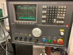
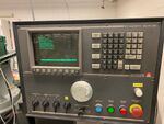
Bridgeport Dynapath Standard Operating Procedure
Axes Definitions
Axes are defined relative to the work piece. If standing in front of the machine and facing it, the x-position increases as the work piece moves towards your left. The y-position increases as the work piece moves towards you. The z-position increases as the tool moves up.
Reference Zero
- Power the machine by flipping the main disconnect, located at the rear of the machine on the right side, top.Template:Clear
- When the computer has booted, press the Mode Select key.Template:Clear
- Press the Fault/Status key and clear the errors by holding down the Override button and pressing the Reset key.Template:Clear
- Press the Mode Select key and press the 0 [zero] key to enter Jog mode.Template:Clear
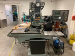
- Note the position of the table and quill in the picture for this step: This is how the machine should look after completing the Reference Zero steps, below:Template:Clear
- Press the R key to enter Reference Zero mode. Note Reference Zero is highlighted in the menu. The z-axis must be referenced first:
- Rotate the Feedrate Override knob counterclockwise until it clicks.
- Rotate the z-jog switch towards positive [+] direction and release.
- Rotate the Feedrate Override knob clockwise and observe that the quill moves up (if it is not already at the reference position). If the quill moves down, press the Motion Stop button and restart this step (ensure the z-jog switch was rotated towards the positive [+]).
- The quill will stop moving and the z-position displayed on the screen will become 0.000, indicating the z-axis is in the reference position.
- Reference the x- and y-axes:
- Rotate the Feedrate Override knob counterclockwise until it clicks.
- Rotate both the x- and y-jog switches towards the positive [+] and release.
- Rotate the Feedrate Override knob clockwise and observe that the table moves towards you and towards your left hand (if both axes are not already at their reference positions). If the table moves towards the right or towards the machine, press the Motion Cancel button and restart this step (ensure the x- and y-jog switches are rotated towards the positive [+]).
- The table will stop moving and the values displayed for x- and y-positions will both be 0.000 when the axes are in their reference positions.
Jogging
Loss Prevention
- Personal Safety: Do not place your hands in a position where they will be pinched between moving and stationary parts. The machine produces enough force to crush bones.
- Breakage: Start movements slowly and increase speed only when confident that the direction of motion is correct and there is no risk of collision.
- Housekeeping: Keep the work area clean, especially the table.
Procedure
- Press the Mode Select key and the 0 [zero] key to enter Jog mode.
- Select the Jog method: Slow, Medium and Fast will allow continuous motion as long as a jog switch is active. The incremental jog methods will move the selected increment once each time a switch is activated.
Continuous Jog (Slow, Medium, Fast)
- Rotate the Feedrate Override knob counterclockwise until it clicks.
- While holding the desired axis jog switch in the desired direction, rotate the Feedrate Override knob clockwise while observing that the work piece moves in the correct direction.
Incremental Jog
- Rotate the desired axis jog switch in the desired direction. Repeat until the desired position for that axis is reached.
Zero Set
Before running a job, the machine must be positioned such that the tool (torch or cutting tool) is positioned at the origin.
- Press the Mode key and the 0 [zero] key to enter Jog mode.Template:Clear
- Jog the machine to the desired work piece origin (determined by the job).
- Press the 9 key and note Zero Set is highlighted in the menu.
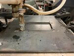
- For welding, set the zero position for x and y at the x-y origin of the part (determined during slicing). Set the zero position for z such that the torch nozzle just touches the substrate (see picture).Template:Clear
- Follow setup practice for setting zero position for machining.
- Rotate the jog switch for the axis (axes) that should be zeroed. Note the position displayed changes to 0.000. Repeat x-, y- and z-axes.
Tool Paths
Rules for Tool Paths
- The Dynapath controller has a limit of 9999.99 mm for any linear axis (X, Y, Z, U, V, W). This is problematic as hundreds of meters of wire can be consumed in a single print. This can be overcome by resetting the U-axis distance using the G92 temporary offset command. If writing tool paths by hand, set the temporary offset before the U-axis reaches 9999.99 mm to zero by inserting G92 U0.000 and then increment the u-axis position accordingly.
- For non-spiral tool paths, alternate the direction of outside shells every layer. For example, odd layers go clockwise, even layers counterclockwise. It is not necessary to alternate the direction of infill.
- If using the Millermatic 190, it is prudent to program dwells (G4) periodically throughout the print. For example, every three layers, insert G4 X120 to pause the machine and allow the welder power supply to cool for 120 seconds.
- A script is being prepared that will alter tool paths such that they meet the above rules.
Uploading Tool Paths
There is a desktop computer attached to the Dynapath controller's serial communications port. A python script (dynapath.py) is used to parse, clean, and transmit tool paths to the controller.
Most tool paths should work as the script strips unsupported commands and attempts to properly format the code for the Dynapath controller. The very first line in the tool path file should be a <8 character name, all in caps and enclosed by parentheses, e.g., (MYFILE). The name must be on the first line and must be alone - no other commands can be on the name line. In the absence of a valid name, the controller will append the file to the catalog with a name starting with P followed by a number.
- Log onto the PC, user name and password are both user0.
- Transfer the tool path to the dynapath/gcode/(your directory name) folder on the PC.
- Right-click on the dynapath folder and select "Open Terminal Here".
- Press the Mode Select button and enter Transmit/Receive mode (8).
- Enter S1 on the keypad and click the Enter key to select the serial communication port as the source.
- Enter T4 on the keypad and click the Enter key to select the part catalog as the destination (target).
- Press the Start Operation soft key, just under the screen. Note the "Busy Receiving" notification on the screen.
- Back at the computer, and in the terminal session, type ./dynapath.py -t -d -n (full path to the tool path file, e.g., /boxes/mytoolpath.ngc) and press enter. If the path was entered correctly, ythe tool path will be displayed line by line as it is transmitted to the Dynapath controller.
- If watching the Dynapath screen, note the line number increments as the file is received, followed by "Done" when complete.
- Press the Mode Select key and enter the Catalog mode (C). If the transfer was successful, note your part file is highlighted, indicating it is currently selected.
Running a Tool Path from the Catalog
- Press the Mode Select key and enter Catalog mode (C).
- Enter the name of the part file you wish to run on the keypad and press enter. Note the file name is high lighted on the screen when it is selected for running.
- Press the Mode Select key and enter the Auto mode (1 - the numeral one).
- Ensure the machine is referenced and the zero position is set (above).
- Ensure there is sufficient wire to complete the print.
- Ensure the wire preload idlers are in place (the springs should be engaged, pressing the idlers against the wire).
- Turn on the welder power source.
- Turn on the argon and ensure there is sufficient gas to complete the print.
- Rotate the Feedrate Override knob counter clockwise until it clicks.
- Press the Start Cycle button. The machine will rapid to the start position and stop.
- Slowly rotate the Feedrate Override knob clockwise off the detent. The machine should start moving and the welder power source should energize as it starts the print.
- If an error with the U-axis occurs:
- Rotate the Feedrate Override knob counter clockwise until it clicks.
- Reset the machine by pressing the Override button while simultaneously pressing the Reset key.
- Press the Reset key again to reset the cursor to the top of the program.
- Retry starting the print.
- If an error with the U-axis occurs:
Welder Setup
- Set the welder to 4 on the voltage dial and 10 on the feed dial.


