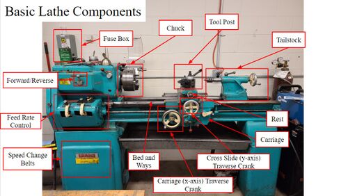
Sheldon Lathe
Safety Precautions/Loss Prevention
Lathes can be very dangerous if used improperly or without extensive training or experience. Please contact foundry staff if you need assistance with the lathe.
- Wear proper PPE throughout duration of operation. Needed PPE includes:
- Safety glasses
- Closed-toed, protective shoes
- Short shirt, long pants
- Observe and learn proper operation by someone trained to operate lathe.
- Keep hands and other objects away from spindle and is operating.
- If you have long hair, please tie it back if are operating or the lathe.
- Never make rapid positioning/axial movements unless aware of end stop.
- Avoid operating lathe distracted (music, double tasking, talking, etc.).
Standard Operating Procedure
Work Holding
A three-jaw chuck is installed on the left side of the lathe track. This set of jaws will automatically center cylindrical workpieces to within 0.003” of the axis of the machine axis. It is important to note that as less volume of your piece is secure in the chuck, more difficult it will be to turn.
- Use specific “T” wrench to close the chuck’s jaws to the approximate size of your sample.
- Place the sample in the vice then tighten the chuck with wrench until your sample is secured and centered.
- Remove the wrench before operation.
Changing Tools and Tool Options
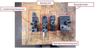
The deformation lab has four types of lathe tools shown in Figure 2 that fit on the lathe’s quick-change tool post.
- Select proper tool for your sample and ensure there are no loose fastenings.
- Slide the tool onto the quick-change tool post while holding longer tool post lever to relieve pressure, almost like a puzzle piece.
- While pressure is still off the tool (tool post lever), adjust the height of your tool using the knurled and standard nuts on the top of tool post.
- Please keep in mind that the cutting bit of the tool should be just BELOW the center of your work piece. Bring the live center near the tool post to gauge this height.
- The angle of the tool may also be altered by loosening the bolt on top of the tool post and turning as needed.
- Retighten post prior to lathe operation by reapplying pressure with the tool post lever.
Feed & Speed
Feed refers to how fast stock is being removed from a piece (lateral motion); speed refers to the RPM of the spindle (rotational motion). The lathe can be changed to a variety of feed/speed combinations. It is good to research which feed/speed is best to be using for your material and purpose. If you are unsure, experiment with your piece at 500 RPM.
Adjusting Speed
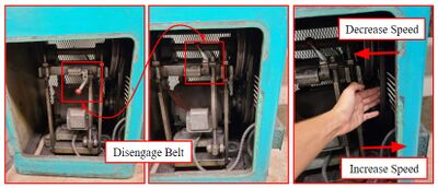
The lathe is usually operated in the “Direct Drive” gear position but moving the gear to low will switch the lathe into back gear. There is a small chart on the side of lathe titled “Spindle Speeds RPM” that lists available speeds. Below are the steps to changes the speed of the lathe:- Ensure lathe is off and open the “Belt Speed” panel (Figure 3).
- Flip the red lever to disengage the belt.
- Adjust the belt to the pullies either to the left or right.
- Moving the belt left will DECREASE belt speed.
- Moving the belt right will INCREASE belt speed.
- Once the speed has been changed and the belt is properly seated on pullies, flip the red lever again to re-engage the belt.
- You may check if the belt is properly seated by spinning the spindle by hand and observing the belt.
Adjusting Feed
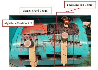
The lathe’s feed rate is controlled by a knob and grid system. There is both an alphabetical and numerical grid. Feed decreases as the knob are moved up alphabetically/numerically. Therefore, “A1” is the fastest feed rate and “F10” is the slowest. The lathe’s feed direction is controlled by a similar system and follows the same steps as feed rate.- With the lathe off, wiggle the feed knobs while turning the chuck by hand. Slowly work the knob to the desired setting.
- Ensure the spindle no longer turns freely, or else it is not in gear.
Tailstock Parts and Operation
The tail stock is the right half of the lathe mechanisms used to hold a work piece in place. Please see the diagram below for an explanation of the parts of the tailstock
There are two tailstock tools available in the deformation lab: a live center tool and a Jacobs (drill) chuck. The live center tool is best for supporting longer work pieces. The Jacobs chuck, more commonly known as a drill chuck, can hold drill bits or reamers that have a shank size of up to 0.5”.
To replace a tailstock tool:
- Turn the crank until the tail stock tool loosens up and the tool can be pulled out.
- Extend the tailstock spindle until more than 1” out of the tailstock.
- Ram the tailstock tool’s taper into the tailstock spindle.
To Drill or Ream with Jacobs chuck:
- Turn off the machine prior to set-up.
- Follow steps above to insert Jacobs chuck into tailstock.
- Use yellow chuck key to tighten drill bit or reamer into chuck.
- Secure your work piece into the three-jawed chuck (left side of lathe) and turn machine on.
- Bring the drill near the face of the work piece.
- Gently bring the drill bit to the face of the work piece and put enough pressure on it to create a small dent.
- This will help guide the drill and reduce wobbling.
- Begin drilling by locking the tailstock to the ways and using the crank to push the spindle into the work piece.
- If there is too much wobble, drill the hole out with a center drill first.
- If the drill bit slips inside the Jacobs chuck, try tightening it further.
Automatic Feed Usage
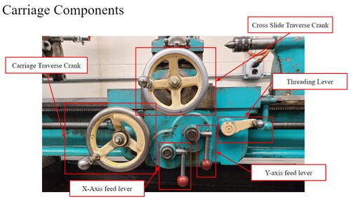
The lathe has settings avaible that will move the cutter/carriage at a fixed rate in a single direction without the user needing to manually control the cutter. Below are the directions to test this option in both the X and y directions.Engaging Carriage/X-Axis Feed
- Position the carriage far enough away from the workpiece that you will be able to test the direction of motion without running into the workpiece, chuck, or tailstock.
- Turn on the spindle.
- Using the leftmost lever on the carriage, engage the feed by pulling the lever out towards you.
- NOTE: THIS WILL BEGIN MOVING YOUR CUTTER.
- If the direction of motion is wrong, disengage the feed by pressing the lever down.
- Stop the machine, adjust the feed direction, and then try again.
Engaging Carriage/Y-Axis Feed
- Position the carriage far enough away from the workpiece that you will be able to test the direction of motion without running into the workpiece, chuck, or tailstock.
- Turn on the chuck.
- Using the rightmost lever on the carriage, engage the feed by pulling the lever out towards you.
- NOTE: THIS WILL BEGIN MOVING YOUR CUTTER.
- If the direction of motion is wrong, disengage the feed by pressing the lever down.
- Stop the machine, adjust the feed direction, and then try again.
Turning
Turing is when a user removes stock radially from a work piece to reduce its diameter.
- Make sure work piece is secure in the chuck.
- Once spindle is on, move the cutting tool closer to the face of the workpiece.
- Use cross-slide dials (located on cutting tool carriage) to adjust the tool to a distance that will remove the desired amount of stock.
- One mark on the dial will yield removing ~0.002” from the piece’s diameter.
- DO NOT try to take off a large amount in stock in one pass. Plan on doing several passes to get piece to desired diameter.
- Either manually or automatically (x-axis feed) move the tool along the x-axis of piece to begin cut.
- Use small amounts of cutting fluid when needed.
Troubleshooting
- While turning, drilling, or reaming a piece, are you hearing a sharp screeching sound?
- Decrease your spindle speed and apply coolant.
- Does your piece have a poor surface finish?
- Leave diameter of workpiece at approximately 0.010" greater than desired diameter. Remove this final bit of stock at half the automatic feed rate you were taking before.
- Make sure the cutting bit is sharp and apply coolant if all else fails. Keep in mind that some materials, like softer aluminum castings, are incredibly difficult to get a good finish on.
- Does your piece keep producing long, curly strings/chips by cutting tool while turning?
- With stronger materials, disengage automatic feed to break the chip away from the tool and discard. These pieces may be very sharp and strong (it is basically steel ribbon), so it can either cause injury to user or machine if not removed before it builds up.
