Vickers Hardness Testing
Jump to navigation
Jump to search
Loss Prevention
- Do not adjust equipment after starting a test
Procedure
Section 1: Instrument Setup
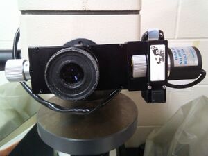
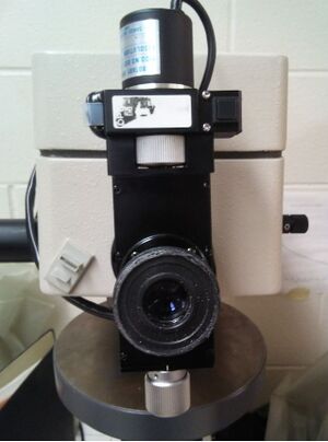
- Existing indentations can be measured using the macro-Vickers scope (figure 1)
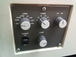
- Check to ensure the proper magnification setting is selected on the instrument. The proper setting is indicated by "(X10)" on the "LENS" knob. Turn the power switch to "ON". This panel can be viewed in figure 2.
- Zero the machine (calibrate) by using the following steps:
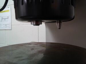
- Position a sample on the stage under the lens, such that no indentation is visible. The lens and indenter can be seen in figure 3.
- Focus the image by moving the stage up and down with the vertical control knob.
- Look into the eyepiece and move the two measurement lines together, using the control knobs on the lens. The lines should JUST touch, so that no light is visible between them.
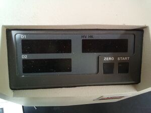
- Firmly press the "ZERO button on the measurement panel (figure 4). An audible beep will be heard.
Section 2: Instrument Calibration
- Microvickers calibration:
- Use a calibration standard before staring the experiment (ID 11564).
- Need hardness of 384±5 to pass.
Section 3: Indentation Measurement
- Position the indenter above the sample in place of the lens and press start.
- Return the lens to its original position and focus the image such that the sample surface is clear (not the indentation itself). This is important such that the edges of the indentation are in sharp focus.
- Starting with the left (or lower) measurement line (controlled by the left/lower knob), move the line outside the indentation, and bring it in slowly towards the indentation until it just touches the corner.
- Repeat step 3 for the right/upper measurement line (controlled by the right/upper knob). Do not move the left/lower line while adjusting the right/upper line.
- Press the measurement button.
- Rotate the measurement knob mechanism 90°, and repeat steps 3-5.

